Do you want to be informed on new Posts on this Thread? (members only)
| S&S Swan Maintenance - Trim tab and locking wheel dimensions for 43 |
|---|
|
Join Date: 15 April 2011
Posts: 393 |
||
|---|---|---|
|
Trim tab and locking wheel dimensions for 43 |
|
Join Date: 16 April 2011
Posts: 31 |
||
|---|---|---|
|
Hi Chris, I don't have plans or specifications, but Firebrand II does have a working trim tab along with the original wheels (see below). If it is of any help, I can provide you with photographs and dimensions of the main components. If necessary, I can also look at disassembling and providing dimensions of the shaft and wheel hubs. Best regards 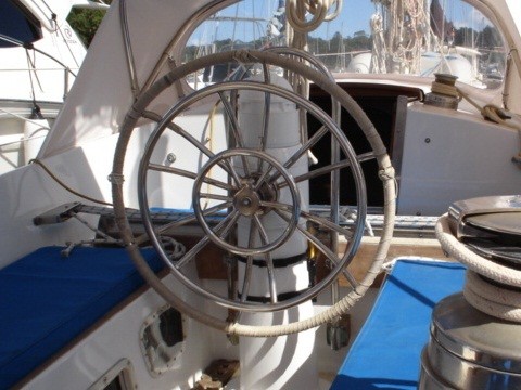 |
|
Join Date: 02 January 2008
Posts: 1547 |
||
|---|---|---|
|
Dear Andrew
|
|
Join Date: 15 April 2011
Posts: 393 |
||
|---|---|---|
|
Hi Andrew,
|
|
Join Date: 16 April 2011
Posts: 31 |
||
|---|---|---|
|
Hi Lars, Yes Firebrand II has a modified cockpit layout. This appears to have been done when she was originally built for Denis Miller. The steering pedestal is forward and the primary winches are inside the cockpit. Apparently, Denis Miller's original Firebrand, which was a timber 43ft S&S from the early 1960s had a similar layout. Interestingly the original Firebrand is still sailing today. Yes the steering cables run aft just under the cockpit floor back to the rudder. The trim tab cables run down under the floor and forward to the trim tab. Best regards |
|
Join Date: 16 April 2011
Posts: 31 |
||
|---|---|---|
|
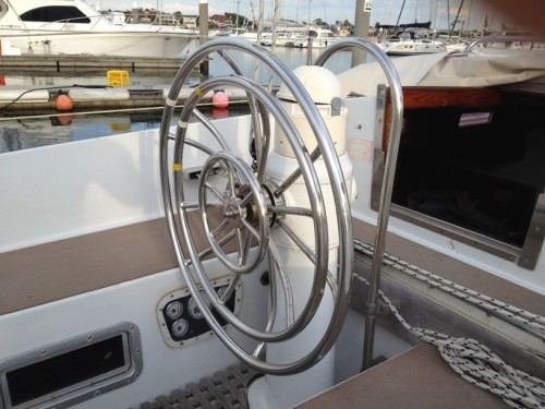
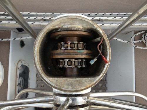
Hi Chris, No problem. It is relatively easy to take a few measurements and photographs. These should give you a pretty good idea of what might be involved. Hopefully, most of the internal workings are still there. Otherwise it could be a fairly significant undertaking. The main dimensions of the wheels are as follows: Outer wheel (rudder) 770mm dia (approx 2ft 6in) The outer wheels appear are made from tube with a diameter of around 23mm. The tube for the inner wheel is slightly thinner at around 20mm diameter. The wheels have six spokes, as shown in photo 1, and are dished so that they are in the same plane, as shown in photo 2. The wheels drive three concentric shafts. The outer shaft drives the rudder via the rear sprocket and chain, shown in photo 3. The middle shaft drives the trim tab via the forward sprocket and chain. There are also two clutches; the first between the rudder shaft and the trim tab shaft, and the second between the trim tab shaft and the steering pedestal. The locking shaft can be wound forward to lock the trim tab-pedestal clutch, effectively fixing the trim tab in place. It can be wound back to lock the trim tab-rudder clutch (as shown), effectively locking the trim tab to the rudder and enhancinhg low speed manouvrability. Or, it can be left in-between allowing the trim tab to be moved independently. I hope this has been of some help. Let me know if you would like me to get more precise measurements. Best regards
   |
|
Join Date: 15 April 2011
Posts: 393 |
||
|---|---|---|
|
Dear Andrew,
|
|
Join Date: 15 April 2011
Posts: 393 |
||
|---|---|---|
|
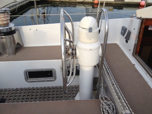
Dear Andrew, I have attached pictures of my steering gear set-up. Based upon what I see in you photos, i am concerned that the main gear rod may have been shortened. I was unable to remove the cap that holds the steering wheel in place and will need to do that in the future. In my brief examination, I see that I will need to remove the pedestal and work hard to bring it back to life. All comments are welcomed. Chris Mabel's Casse Tete 43/003 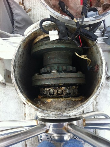 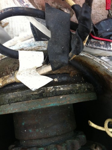 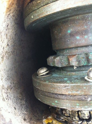 |
|
Join Date: 20 February 2007
Posts: 119 |
||
|---|---|---|
|
Chris:
|
|
Join Date: 15 April 2011
Posts: 393 |
||
|---|---|---|
|
Dear Hiro, Thannk you for your post - I had neglected to select the "notification" buttom and just saw this note. I will look into the maintenance area - i am hoping that the "drawing" to which you referred is there. i am lucky to know of an excellent machine shop close by; the owner does very sophisticated work on racing cars and boats and is willing to take on my small jobs. This may be a larger job but I think he will be able to figure out what I cannot! Yesterday, I removed the fuel tank to get at the large sheaves located just behind the tank; they are totally seized so it was a good decision. I it will also make it possible to clean the area and repair the wood around it. Pictures are attached. One question for you and the group, especially the Professor: what type of material should I use to support the tank? Fair Winds, Chris 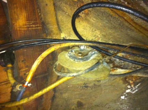 Sheaves 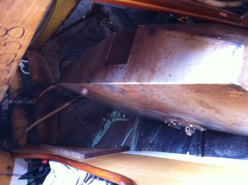 fuel tank removed |
|
Join Date: 15 April 2011
Posts: 393 |
||
|---|---|---|
|
Pictures in previous post were 90 degrees off. 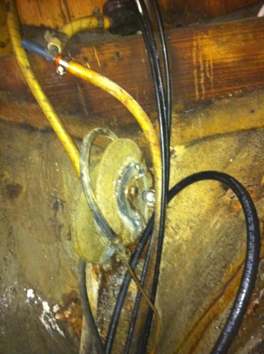 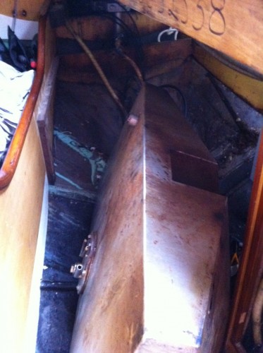 |
|
Join Date: 20 February 2007
Posts: 119 |
||
|---|---|---|
|
Chris:
|
|
Join Date: 15 April 2011
Posts: 393 |
||
|---|---|---|
|
Dear Hiro, Thank you for your note. Answers to your questions follow. Are the other trim tab sheaves in good nick? - Some are missing and the two large ones you can see in the picture I provided are seized. I will need to do some work here. My goal is to get set up so I can make the trim tab operable, not necessarily get it fully functional this season. having said that, Since I need to remove the pedestal, it may all happen sooner than later. Thank you for looking for the diagram - I will look for it in my email. With warm regards, Chris |
|
Join Date: 15 April 2011
Posts: 393 |
||
|---|---|---|
|
Dear Members, I sent a package of material, including pictures from this thread and the diagram supplied by Hiro, to the machinist who has helped me with other projects on the boat; he replied that, yes he could help and yes he understood how the mechanism worked and that he would help me. He also know of an individual who can fabricate the wheels. Now, this may happen soon or it may happen next winter, but I think it will happen. Thank you for all the help and please look for updates. Chris |
- Threads : 1702
- Posts : 10217
- Members: 821
- Online Members: 0