Do you want to be informed on new Posts on this Thread? (members only)

S&S Swan Maintenance - Boat Electrical system a mess - New Panel needed
10 April 2013 - 14:24
#1
Join Date: 15 April 2011
Posts: 393

Boat Electrical system a mess - New Panel needed
Dear Members,
I just purchased a new battery charger, the old one had stopped working after an electrical fire in the engine room; I had hoped that my new engine harness and engine panel, along with cleaning all connections and replacing battery cables; etc, had been sufficient to allow for a simple installation - not so. I examined the shore power connections and the distribution panels - all a mess!

So, a few questions: Blue Sea seems to be the panel of choice here. Do you have any recommendations?

There was no galvanic isolator in the green grounding line. Do you all use one? It seems prudent to incorporate this device.

Finally, I have several books on marine electricity, both DC and AC but none shows actual pictures - it's all diagrams. I need technique - If I am going to re-wire the boat, I would like it to look as good as Swan's work - Any suggestions?

Thanks,

Chris

10 April 2013 - 21:41
#2
Join Date: 27 January 2011
Posts: 140

Hi Chris,

last year we added a galvanic isolator and a leakage circuit breaker to our shore power setup. At the moment I am working on standardizing the 220V sockets. We have a mix of French, German and UK sockets on the boat. A funny indication of previous ownership, but it requires a number of adapters at board.

Christian IF 411/028

11 April 2013 - 05:30
#3
Join Date: 20 February 2007
Posts: 119

Hi Chris:

It looks as though you are going through the same issues as when I was updating my boat.

I opted for a new Paneltronics circuit breaker panel with customized breaker sizes per my own spec. It has been a faultless unit. You can see photos in the Swan 43 maintenance section of this web site.

I used Nigel Calder's book extensively when doing my re-wiring.
In anticipation of wiring efficiency degredation over time I sized all of my wires based on the 3% loss not the 10%. The wires get a little heavy with this design but I did not want to have to replace these wires during my ownership. Also took the time to use the correct ABYC color coding for the new wires based on intended use such as lighting, pumps, electronics, etc. DC Ground is always yellow.

I opted not to have any AC shore power or AC devices on board the boat so did not plan the wiring for it.

Regards,

Hiro


11 April 2013 - 06:23
#4
Join Date: 16 May 2009
Posts: 252

Hiro -

No AC at all, even for battery charging? Do you have a wind or solar charger to keep the voltage topped up? A couple of questions come to me from other notes on this thread - the main one being is there an easy way such as an adaptor for a US boat with AC to plug into Euro 50 cycle power?

Thanks to all, let's go spring, and let's go sailing!

Geoff, Corazon, 411 #41

11 April 2013 - 14:03
#5
Join Date: 15 April 2011
Posts: 393

Dear Christian (my full name too!),

Thank you for your reply.  Yes, i agree, it's time to add the galvanic isolator.  I have done a little research since I posted and it seems that the Fail-Safe designation is the type to get.  For around $200 USD I think I can include an isolator in my grounding line.

It also seems that the isolator may help in the case of an AC short which may not be apparent but is allowing 110 volt current to be flowing into the surrounding water; a danger for swimmers.  Although, I really can't imagine anyone swimming in the water near my boat!

Chris

11 April 2013 - 14:14
#6
Join Date: 15 April 2011
Posts: 393

Dear Hiro,

Thank you.  As soon as I finish this note, I will immediately look at the maintenance section of this site to see your wiring project; I know it will be informative. 

With regard to AC, it came with the boat.  I owned a Tartan 41, similar to our boats but not as seakindly, in the '80's which had only DC.  I didn't miss the AC at all.  My last boat had AC and I really didn't use it much.  Now, however, I spend a lot of time at the dock and therefore will use the battery charger; etc.  But...I think I could almost convince myself to make the change back to DC only - I had not even thought of that.

Nigel Calder's books were my bibles while living aboard - those copies are gone so I need to get new ones.

I like your idea of over-sized wiring and certainly color coding.  When my business partner asks why I don't have someone else do the work, asside from the cost which is a big factor, there are so few really good mechanics, electricians; etc., that I find it's just easier to educate myself and do the job.

Re-wiring, however, was not in this year's plan!  So, I am really struggling to figure out how to get everything done.  I need to stop all the leaks at the deck or all other work is moot.

Thanks again.

Chris

11 April 2013 - 14:55
#7
Join Date: 15 April 2011
Posts: 393

Hi Hiro,

I am embarrassed to say that I could not find the electrical section you mentioned.

Chris

11 April 2013 - 15:41
#8
Join Date: 20 February 2007
Posts: 119

Sorry everyone I thought the new electrical panel image was posted already on the web site but it is not.

Here are the images.

I have never had an issue with running low on DC power. I must point out that I do not have any power hungry devices aboard such as refrigeration. I did however re-lamp all light fixtures including running lights to LED which made a huge impact on power consumption. I run a laptop with a navigation software plugged into a DC cigarette lighter socket (not AC through an inverter) and the batteries will be fine for at least 12 hours before charging with engine alternator (100 amp high output) for about an hour of running time. I have no solar or wind generators.

I guess my philosophy has been for power efficiency and conservation rather than power generation.

Regards,

Hiro

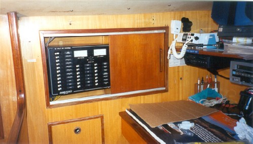
New Paneltronics electrical panel

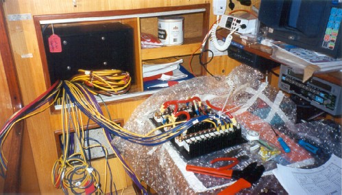
New wiring in progress during new panel install

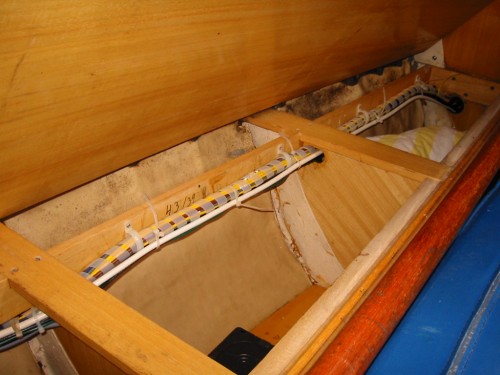
New main wiring loom going forward (not in bilge)

11 April 2013 - 16:01
#9
Join Date: 20 February 2007
Posts: 119

Here is the wiring schematic I used for my new wiring.
I am not an engineer so please forgive the amateur drawing.

Hiro

Wiring schematic for Hiro Maru

11 April 2013 - 16:04
#10
Join Date: 20 February 2007
Posts: 119

Sorry everyone forgot this site does not like pdf files.
Here is the image in jpg.

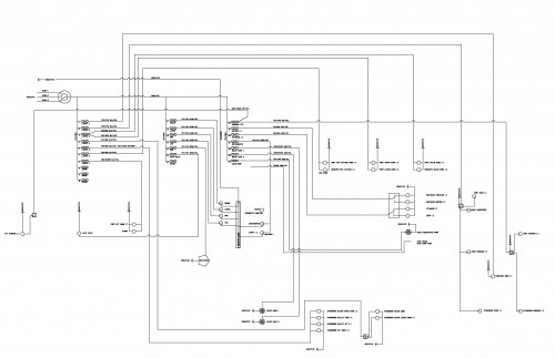
Hiro Maru amateur wiring schematic

11 April 2013 - 21:10
#11
Join Date: 02 January 2008
Posts: 1547

Dear Geoff
In order to connect to 220 V 50 Hz AC you need a transformer reducing the voltage to 110 V on board, but the transformer does not change the frequency, and you must avoid using AC devices which can not take 50 Hz. Battery chargers usually accept both frequencies, but for example microwave ovens do not.
If you also want to change the frequency there are shore power converters able to do this, but they are intended for much bigger yachts.
The proper way is to install a separate shore power inlet for 220 V, and mark both inlets clearly.
Kind regards
Lars


Dear Chris (Colton)
Christian (IF) mentioned that he installed a leakage circuit breaker. The technical notation for this is GFCI (ground fault circuit interrupter), and it is strongly recommended that you too include such a thing. This refers also for all shore power installations not having one. The GFCI will switch off in case of leakage before life-threatening shock occurs. It will not protect you, however, if you touch hot and neutral.
Kind regards
Lars

12 April 2013 - 16:51
#12
Join Date: 15 April 2011
Posts: 393

Dear Professor,

Thank you. My boat currently has GFCI outlets installed.  I plan to replace all of the AC outlets.  I am also aware of a GFCI breaker, are you referring to both?  I am not really sure where such a breaker would be inserted – possibly it is the main breaker on the distribution panel.

I just ordered the galvanic isolator - fail safe model which meets ABYC 2008 standards - and expect to receive it early next week.  Then I will begin to wire the AC and then the battery charger. My original plan was so simple - replace the battery charger!

Thank you for your concern and for mentioning the ground fault interrupter - I do not consider myself an electrician; I have my books and I read a lot, and I have a healthy fear of AC electricity. That's not enough; with your comments, help from members of this forum and the help of my friend here in the US who is an electrician, I can do the grunt work but have a professional check it all out!

With warm regards,

Chris

13 April 2013 - 08:59
#13
Join Date: 27 January 2011
Posts: 140

Hi Chris,

we installed a GFCI centrally, securing the complete the 220V distribution. There is plenty of information about this subject on the net. I was not aware that there are also GFCI outlets, as you seem to have on your boat. One article on the subject: GFCI.

I am following all your projects on this forum, and I am equally impressed by the challenges you are confronted with, and your courage and determination to tackle them all over time.

Christian IF 411/028

14 April 2013 - 13:48
#14
Join Date: 15 April 2011
Posts: 393

Dear Christian,

Thank you for your note and kind words.  I will read more about the central GFCI and have the Admiral (wife) find one as I continue to amass all the upgrades to my electical system.  I expect that this project will not be started until later this summer.

In the mean time, I continue with other projects; yesterday, I removed the fuel tank so that could inspect the sheaves for the trim tab.  This was fortunate since the sheaves were totally seized.  Since it's all clear in that area, i plan to clean and paint the area below the tank - almost fifty years of debris, oil, water and grease makes for a truly magnificent mess!

I think ignorance may be my greatest driver!  I have no idea what I am getting into until after it's too late!

I will post picture in a different thread!.

Thanks again.

Chris

15 April 2013 - 17:45
#15
Join Date: 02 March 2007
Posts: 83

Dear Chris,

I also am rewiring quite a lot of my 41. The replacement of the toerails meant removing the wiring panel to get at the bolts. The result was a complete mess of unmarked wires, 30 years of additions and modifications. The engine wiring was worse, with a lot of new wires run through the bilges to reach the instrument panel.

The original Nautor wiring was a massive harness, stretching from the engine panel ( which also had all the navigation light switches) through to the main switch panel and then to the engine. This was evidently made off the boat, and had all the taps off the harness at the correct points, with all the wires marked according to the wiring diagrams, which I still have. The wires were bare copper, with the result that a lot of them had deteriorated with the brown oxide coating which cannot be removed.Very few wires in this harness were still doing anything, so I removed it completely.

My hints for rewiring are:

1/ Draw a detailed schematic showing every connection. Do all the thinking off the boat. Consider the physical attachment of the cables to the various instruments and equipment. If possible , use soldered connections rather than crimps. If you have to use crimps ( and some are inevitable), use the proper crimping pliers. Don't try and put too many cables in a terminal block that is too small. Use the best quality terminal blocks which have a leaf spring to protect the wire.
2/- Plan a number of small wiring harnesses rather than one large one. Consider using a multiway plug and socket if an item might need to be removed. An example of this is the engine control panel. I rewired my panel using all soldered joints, and connected a 16 way plug on to the wiring tails. There is a matching socket on the engine wiring harness, which just goes to the engine. This means the engine panel can be removed for service by undoing one connector. I have a similar arrangement between the main switch panel and the wiring box ( plastic box to IP68) which lies behind the panel.

3/- Consider using relays to switch high current items. Examples are autopilot, starter solenoid,engine blower and Thermostart. This means that the long lengths of wire to the switch panels can all be a small size. I used 14AWG tinned copper wire throughout for the engine wiring.

4/- Label all wires with clip on number tags and/or colour coding. Keep the schematics up to date for the benefit of the next owner!

5/ Don't think that everything has to be wired directly to the battery, in spite of what manufacturers instructions often say. The Swan 41 has 50sq mm battery cables running to the master switch under the chart table seat. I added a domestic 100A two pole terminal block next to the fuse block to take all the high current connections such as fridge and bilge pump.

I hope these hints are useful. I am an electronics engineer, and have rewired several boats, so I have had some experience before.

regards

Cosmo Little

15 April 2013 - 21:06
#16
Join Date: 15 April 2011
Posts: 393

Dear Hiro,
You do fine work. Thank you for posting your pictures and diagram. I cannot actually read the schematic and would like to see what you have done - could you email it to me? Also, what program did you use to create the schematic? I may end up drawing mine on a drafting table - an electronic file would be better!

Thanks,

Chris

15 April 2013 - 21:21
#17
Join Date: 15 April 2011
Posts: 393

Dear Cosmo,

Thank you for your note - do you want to re-wire my boat too? I think I have a slight advantage over you in that my boat was re-wired with tinned wire in 1985 - it's really the overload on the panels that needs to be addressed. A few circuits also need to be evaluated, upgraded and re-routed. Having said that, it is a mess at the panel and I like your suggestion of drawing the schematic first. Right now, it is virtually impossible to know what's what.

I have a new engine panel and harness which makes me very happy - especially since it has an alarm that works. I found that out when I lost freshwater and the engine began to over heat.

I am concerned the that i could experience another electrical fire (I described one in the engine room) and have decided to move this project up ... a little, anyway.

I will save your message and review it as I begin.

In the books I have, there seems to be a conspicuous absence of practical application techniques. For example, in speaking with an electrician, he recommended that instruments go on one breaker but that the circuit be run through a breaker box so that each instrument could be fused properly and so that fewer wires gang up on one stud. Sounds like great advice.

I especially liked your suggestion of labeling everything.

Thanks again.
Chris

17 April 2013 - 05:06
#18
Join Date: 20 February 2007
Posts: 119

Sure Chris.
Send me your email again.

Thanks,

Hiro

17 April 2013 - 05:43
#19
Join Date: 20 February 2007
Posts: 119

Hi chris:

I created the wiring schematic using Autocadd.

Also one of the criterias during my re-wiring design was to separate the electrical functions so if there were to be a circuit failure it would not take out an entire system. For example the lighting circuit down inside the cabin were split port and starboard so if a circuit failed I would still have lights in any given space albeit on side. One circuit controls the port main salon lighting, another the starboard salon lighting, etc. Same with bilge pumps (one circuit for bilge pump #1 and another circuit for bilge pump #2), navigation lights (I have a mast head tri-color on one and the deck level nav lights on another circuit. Obviously circuits with dedicated items such as the auto pilot, single side band radar, radar, VHF are not split but only serve that one item.

Also my engineering friend suggested that ideally it is best to not over load one bank or circuit with lots of amperage drawing items. Instead distribute items on each bank or circuit so they have relatively balanced amperage loadings.

I also labeled each wire as mentioned in this forum.

Although I did not solder my connections I did but use the ratcheting type crimping tool and sealed all connections with adhesive lined shrink tubing.

It took me over a year to figure out the desired wiring layout and the location of necessary holes in bulkheads (off the boat) on paper. Then I did the re-wiring over one winter and it went pretty quickly. The longest part of the re-wiring was the cutting of holes in bulkheads with a hole saw and then coating the hole opening with west epoxy to seal the exposed raw laminates of the wood bulkhead. This had dual purpose in that first the laminates would not be affected by any water damage and secondly it creates a smooth surface so no other hole protection such as grommets are necessary to protect the wiring from chafing against the new opening.

Also remember to run a couple of spare wires down to each remote area as a spare for future before wrapping the wiring loom bundle in armor. Same concept with installation of a couple of extra circuit breakers for spares and future.

Sounds like a big job but it really is not that bad.

Regards,

Hiro

17 April 2013 - 07:59
#20
Join Date: 30 January 2007
Posts: 461

Hi Hiro,
I am very impressed, it sounds like you took all the best choices!
The only comment I have is that you did not mention the kind of wire you used. As it seems that you strictly followed ABYC indications, I assume it is a tinned wire for marine use.

Daniel, 411/004

17 April 2013 - 13:54
#21
Join Date: 15 April 2011
Posts: 393

Hi Hiro,

christianjcolton@gmail.com

On a separate note, I may be in CT for the wooden boat show at the end of June. If so, would you like to meet?

With warm regards,
Chrs

  • Threads : 1702
  • Posts : 10217
  • Members: 821
  • Online Members: 0