Rudder Gland (Part 2) Dear all , Dear Professor, we are trying to solve a leak from the rudder gland on a 48.
The leak seems to be mostly from the thread, rather than between the shaft and the gland nut.
I have 2 specific questions -
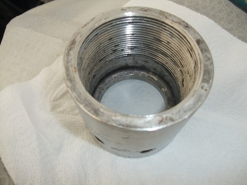
First should the stuffing be just at the top of the nut - where it has been machined to be flat (see first picture) - there is enough space for 3 stuffing layers, or is it better to put more but where the nut is threaded.
Second - the top of the rudder tube is just the (rough ) end of the pipe - should there be a washer between this and the stuffing ?.
Of course any other comments would also be welcome.
Dear Sergio
The stuffing works best in the smooth area near the top, but pls note that it will be compressed when the nut is tightened. Therefore put in one or two more layers than you mention.
If the upper end of the rudder stock tube is rough something has happened, it should be smooth with a recessed plastic bearing sleeve around the stock and flush with the tube upper surface. The stuffing should rest on this smooth surface, no washer required normally.
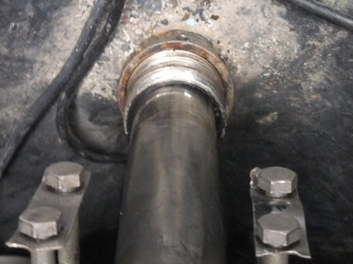
Based on the second photo it appears that also the plastic bearing sleeve is uneven at the upper end. Has it been attempted to dig it out, damaging the sleeve and tube end in the process? The bearing sleeve sits in a deep machined recess in the tube, and replacement requires that the entire sleeve is taken out. If this can not be done with the rudder stock in position the rudder and stock must be dropped.
The smoothness of the rudder stock needs to be checked in this area, if uneven this will damage the bearing and the seal.
Would appreciate your comments to my guesses, and close ups of the uneven surfaces.
Kind regards
Lars
Dear Lars, thank you for your reply.
I think that your guess is right , but I will take some more pictures to show you the problem. Here some more info: the shaft diameter is around 60 mm and the internal part of the gland is around 72 mm. I used therefore a 6 mm non graphite stuffing on the inside.
The problem I think it is due to the fact that when I had the rudder serviced by a major UK shipyard they replaced the main bearing inside and they probably just didn't checked carefully the recessed plastic bearing sleeve and replaced it with a non recessed one. Since that moment , I always had problem of water coming in from the gland in the region of around 30/40 ltrs per hour ( only when motoring).
As you noticed now the bearing sleeve is worn on one side . There is a 1/2 mm play but more that a worn sleeve it seems that the shaft is not centred with it.
The shaft is not bended because when I turn it the play is still on the same side.
Do you think it is possible to take off the sleeve ? And in positive case what should I use as a replacement ( it seems to me that to machine a new one out of a Tfp bar it would be quite difficult because of the very thin dimensions required)
Some pictures will follow shortly. Very kind regards. Sergio
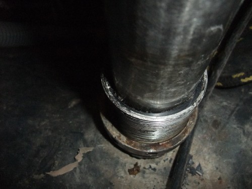
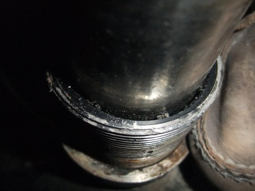
Dear Lars Here we have some close-ups of the top of the tube.
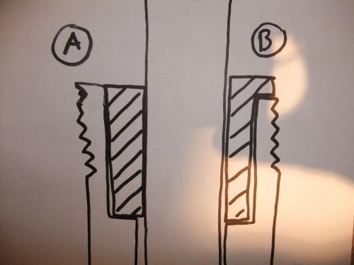
I would also like to be clear if the recessed plastic bearing is flush with the pipe (A), or shaped to fit above the pipe (B).
Regards Sergio.
Dear Sergio
Thank you for the additional photos.
You said this "bearing sleeve" was installed by a major yard. I think you should have a serious discussion with them about getting a proper one.
If the shaft is not held at the center of the tube it will rub on the gland, and there is a shiny band on the stock that indicates where this occurred.
It should not be difficult to get the sleeve out, the big slot allows a hook to be inserted and turned so it bites into the plastic, then pull.
The original concept was according to "A", but "B" is also a possibility provided the tube end is flat and smooth.
The recommended material for a new sleeve is POM, polyoxymethylene, one trade name is Delrin, and tubes should be available reducing wasted material.
Correct tolerances are important for the sleeve.
The thickness of the stuffing band should be equal to the width from the stock to the outside of the thread. In the photo it appears to be more than 6 mm, according to the information I have it should be around 8 mm, pls check.
After the sleeve has been removed it should be checked whether the shaft is now centered in the tube. If not the bearing at the top end of the stock needs to be released so the stock is free to move there. Center the shaft in the tube and check what position the shaft takes up at the top end, and whether the top bearing can be installed in this position.
Kind regards
Lars
Dear Lars, thank you for your additional advices. I will contact the yard to check with them about this problem and will inform the forum accordingly.
Before removing the Bering sleeve I would like to check about the availability of a replacement one.
You mentioned the possibility of finding alreading existing Derlin tubes. Can you tell me where or do you have a contact name or Internet address?
Kind regards
Sergio
Dear Lars
At the risk of sounding stupid, can I clarify the construction of the steering;
Is the plastic sleeve the 'top bearing' or is there another brass one lower down?
As far as I can tell, the movement (play) in the shaft is limited by the plastic sleeve, so if there is another bearing, it is not doing much at the moment.
Dear Sergio
The plastic bearing in the photos is the mid bearing, and it supports the shaft at that level.
There are also bearings at the bottom of the skeg, and at cockpit floor level, the latter is the top bearing.
Kind regards
Lars
The top bearing has been mounted on top of teak, so it would seem there is scope for misalignment. It also means the bearing is partly on the square section used for the emergency tiller.
I have now found the invoice from the yard, and they talk about replacing 4 bearings, Top, Bottom and 2 in the tube. Does this make any sense to you or are we looking at some unofficial modification that has been done at some time.
Dear Sergio
Yes it is possible that there is a bearing sleeve also at the lower end of the tube. May be difficult to see and possibly require that the rudder is lowered some distance in order to become visible.
Kind regards
Lars