Do you want to be informed on new Posts on this Thread? (members only)
| S&S Swan Maintenance - Mast and steel frame repair |
|---|
|
Join Date: 05 August 2010
Posts: 162 |
||
|---|---|---|
|
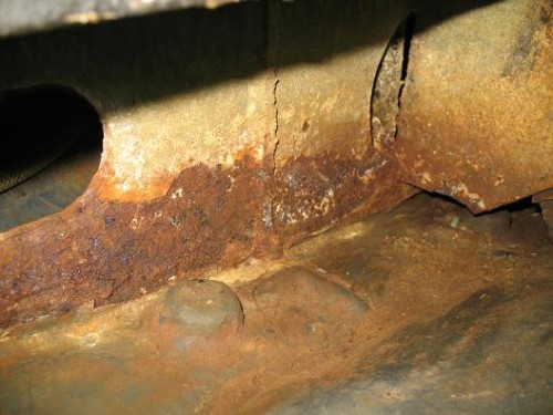
Mast and steel frame repair just a brief note here: I started a thread on February 7th (G10 or G11 on a mast foot) to describe the problems a corroding steel frame caused on our 48. I have just uploaded a description of the repairs with some pictures to the same thread. So now everything is in one thread -- however, as the thread was started some time back, I thought I'd alert you to it, particularly as mast and frames become topics again ... Best regards, Martin
|
|
Join Date: 02 January 2008
Posts: 1547 |
||
|---|---|---|
|
Dear Martin
|
|
Join Date: 16 May 2009
Posts: 252 |
||
|---|---|---|
|
Great catch, Lars - good eye. It sure does look like it needs to be beefed up. Even if the math says no, it would be a good idea, but my guess is the math will say yes. We are very lucky not only that you answer all manner of questions and help us all as you do, but that you look at things like this and alert us to possible problems before they become dangerous. |
|
Join Date: 05 August 2010
Posts: 162 |
||
|---|---|---|
|
Thanks for the caveat, Lars ... and sorry for the delay. Here are the data: - the vertical supports are welded both to the bottom and the top plate;
I hope they don't need to be strengthened as they are stronger than the part we cut out ... which looked original, at least. Best regards,
|
|
Join Date: 02 February 2007
Posts: 202 |
||
|---|---|---|
|
Hello Martin.
|
|
Join Date: 02 January 2008
Posts: 1547 |
||
|---|---|---|
|
Dear Martin
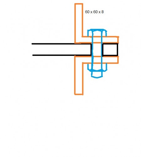 Sketch |
|
Join Date: 05 August 2010
Posts: 162 |
||
|---|---|---|
|
Dear Lars, thank you for the valuable input! Your explanation (as usual) is perfectly clear ... even laymen as I am one can follow.
Best regards,
 |
- Threads : 1702
- Posts : 10217
- Members: 821
- Online Members: 3