
Do you want to be informed on new Posts on this Thread? (members only)
| S&S Swan Maintenance - Heating system Swan 48 |
|---|
|
Join Date: 05 April 2010
Posts: 9 |
||
|---|---|---|
|
Heating system Swan 48 Dear friends, does anybody know if there was a orignial way or a drawing where to put the pipes of the heating system, the exhaust, etc.. We have some remaining signs of a former existing heating system but we would like to renew it in the next weeks. Any information on that would be helpful! Ulli |
|
Join Date: 05 August 2010
Posts: 177 |
||
|---|---|---|
|
Dear Ulli, supposing that while not having the drawings, some experience with installing a heating on a 48 might help ... We installed a new heating system two years ago. In preparation, I found all the holes that were intended for the air ducts on the port side of the boat. They have diameters of about 10-11 cm. Starting (or ending) at the aft bulkhead under the port berth in the aft cabin (see pic), they lead forward to the front cabin. If needed, I can post more pictures, but provided Themis has the same arrangement, you will find them. So I installed a water-based heating (in the stern locker) with four separate heat exchangers (and fans) in the aft cabin, the saloon, the front head and the front cabin. The tubes for the water circuit make use of the holes for the old air ducts. That will not help you, but if you need any pictures of the installation or how the heating unit is installed in the locker, let me know. Best regards from Bremen,
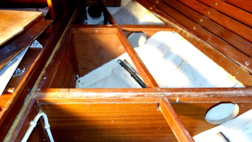 openings for the air ducts under the portside bunk in the aft cabin |
|
Join Date: 11 November 2010
Posts: 23 |
||
|---|---|---|
|
Hi Martin Happy new year. Just about to install a Webasto ThermoPro 90 water heating system to Snow Wolf. Like you we have the air ducting holes on the port side from a system that was removed a long time before I got the boat.
Any pictures of where you fitted the exhaust outlet or any things you would do differently would be appreciated.
|
|
Join Date: 05 August 2010
Posts: 177 |
||
|---|---|---|
|
Happy New Year to you as well! I'll quickly attach a picture of the exhaust position for the Webasto heater. As you can see, it is left of center in the transom (the round opening next to Vellamo's home port). We have the heater mounted in the stern compartment, so the exhaust pipe is as short as possible, includes a gooseneck to prevent water flowing back into the heater, and the through-hull is still easily accessible. I'll think about what I'd do differently and post asap. Best regards, 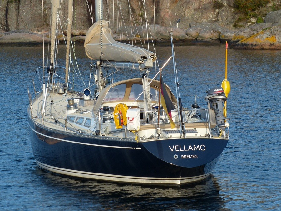 Stern view, exhaust through-hull next to home port line |
|
Join Date: 05 August 2010
Posts: 177 |
||
|---|---|---|
|
Two more sketches of the heating installation on Vellamo. We built the heating system in two stages. First we only went along the port side of the boat; there are four heat exchangers and a total of nine air vents. The hot water tank is connected to the heating so we can produce hot water either by shore power, by the engine, or by the Webasto heating. The heating circuit is run with anti-freeze instead of water and has an own boiler that can "pre-heat" the circuit by shore power. On the second sketch you can see roughly whereabout the components found their place. The circuit runs (and descends) from the burner in the stern compartment under the bunks on the port side, then rises again in the fore cabin to cross to starboard, and from there descends again to the starboard aft bunk. The rise in between required an additional circulation pump. If I'd do it all over, I'd make sure the pipes are close to the hull more or less following the waterline -- that is where the condensation maximizes. I'd make sure there is either warm ventilation or at least a warm pipe in all the lockers. And I would probably build a single circuit (port side forward, starboard back) instead of the two-way we have now, saving half the length of pipe. I hope the sketches are clear enough -- if not, just ask. Best regards,
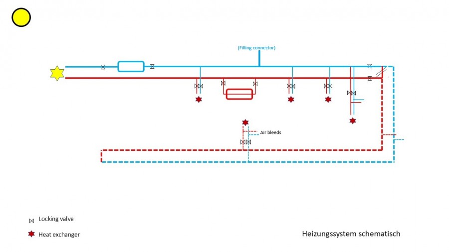 First stage (solid lines) and extension (dotted lines) 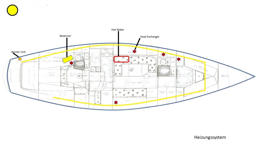 Heating circuit |
- Threads : 1804
- Posts : 10761
- Members: 862
- Online Members: 0
