Do you want to be informed on new Posts on this Thread? (members only)
| S&S Swan Maintenance - Exhaust system on swan 65 |
|---|
|
Join Date: 30 March 2019
Posts: 4 |
||
|---|---|---|
|
Exhaust system on swan 65 Dear All, Cassiopéia, hull 65-14 is fitted with a volvo penta TAMD 41 wich gives 200 HP. She is also fitted with a dry exhaust system wich need to be replaced. I would like to change for a wet exhaust system, but considerind the engine's position far bellow the water line, i don't know how to do that properly. Does one of you already do this on a swan 65, and if so what kind of solution did you use to be sure thad no water comes in and to keep a proper back pressure ? Thanks for your advices. Yann |
|
Join Date: 02 January 2008
Posts: 1547 |
||
|---|---|---|
|
Dear Yann The present exhaust goes out through the SB topside. This blocks the exhaust when the yacht heels to that side, and a broach may fill it.
The suggestion is to modify the system so it exits both sides, and arranged so it passes above the aft cabin door opening.
A wet system with a water separator reduces the exhaust back pressure, this is helpful for the turbo engine, and a nice feature in harbour - no sloshing water.
A siphon break is also required if the system is dry now.
More detail available if required
Kind regards
Lars
|
|
Join Date: 30 March 2019
Posts: 4 |
||
|---|---|---|
|
Dear Yann The present exhaust goes out through the SB topside. This blocks the exhaust when the yacht heels to that side, and a broach may fill it.
The suggestion is to modify the system so it exits both sides, and arranged so it passes above the aft cabin door opening.
A wet system with a water separator reduces the exhaust back pressure, this is helpful for the turbo engine, and a nice feature in harbour - no sloshing water.
A siphon break is also required if the system is dry now.
More detail available if required
Kind regards
Lars
Dear professor,
Thanks a lot for your answer. I would like to go further with your suggestion. first, where do you sugggest to place the two exits you are talking about ? and two, wich elements would you suggest to use to build this exhaust line.
I agree that the dry exhaust melody is funny for 10 or 15 mn,
Waiting to read you, Kindly Yann |
|
Join Date: 02 January 2008
Posts: 1547 |
||
|---|---|---|
|
Dear Yann It is suggested that you make another exhaust exit on the opposite side in about the same location, depending on easy routing of the hose. The through-hull can be just above the boot top stripes (assume this is the case on SB side), and can well be of GRP. Installation possible with the yacht in the water provided she is heeled a little bit to the other side.
You will need the following parts:
- A wet exhaust bend on the engine with water injection connection. The hose diameter is probably 4", but this needs to be checked. 3½" used for the older engines of this type.
- Approved wet exhaust hose of the same diameter, length from engine down to the water lift, up to the water separator, and further up to the highest point at coachroof level.
- A temperature alarm on the exhaust bend, warning audibly if there is a lack of cooling water.
- A water lift/silencer with sufficient capacity to contain all the water flowing back from the hoses, and equipped with a drain cock
- A water separator for the same hose size. Water lift and separator can both be acquired from the same supplier, http://www.halyard.
- A T-connection with a 180 degree bend for the top end. Will make a sketch. The hoses may run on opposite sides of the bulkhead if this is easier.
- Hoses from the top end down to the through-hulls both sides. These hoses could be one size smaller if their diameter is difficult to accommodate. To be run without forming water pockets, i.e. steadily descending.
- A siphon break arrangement for the exhaust cooling water, sketch will explain.
It is likely that the dry exhaust now heats up the interior quite a lot, this will change when you go to a wet system. Is the propeller set to limit the maximum rpm to 3250? This is the recommended Medium Duty setting for this engine.
The yacht appears to float in a bow down position, is there much anchor chain in the bow, or internal ballast?
Kind regards
Lars
|
|
Join Date: 30 March 2019
Posts: 4 |
||
|---|---|---|
|
Dear Yann It is suggested that you make another exhaust exit on the opposite side in about the same location, depending on easy routing of the hose. The through-hull can be just above the boot top stripes (assume this is the case on SB side), and can well be of GRP. Installation possible with the yacht in the water provided she is heeled a little bit to the other side.
You will need the following parts:
- A wet exhaust bend on the engine with water injection connection. The hose diameter is probably 4", but this needs to be checked. 3½" used for the older engines of this type.
- Approved wet exhaust hose of the same diameter, length from engine down to the water lift, up to the water separator, and further up to the highest point at coachroof level.
- A temperature alarm on the exhaust bend, warning audibly if there is a lack of cooling water.
- A water lift/silencer with sufficient capacity to contain all the water flowing back from the hoses, and equipped with a drain cock
- A water separator for the same hose size. Water lift and separator can both be acquired from the same supplier, http://www.halyard.
- A T-connection with a 180 degree bend for the top end. Will make a sketch. The hoses may run on opposite sides of the bulkhead if this is easier.
- Hoses from the top end down to the through-hulls both sides. These hoses could be one size smaller if their diameter is difficult to accommodate. To be run without forming water pockets, i.e. steadily descending.
- A siphon break arrangement for the exhaust cooling water, sketch will explain.
It is likely that the dry exhaust now heats up the interior quite a lot, this will change when you go to a wet system. Is the propeller set to limit the maximum rpm to 3250? This is the recommended Medium Duty setting for this engine.
The yacht appears to float in a bow down position, is there much anchor chain in the bow, or internal ballast?
Kind regards
Lars
Dear professor, if i well understand, first, i have to change the outlet after the turbo to have an elbow with water injection, I planed to install a riser on this elbow, that will rise for about 200mm The exhaust bend seems to be a 3,5inch one.
second: under the floor beetwin the galley and the chart table, a water lift will take place. then the hose will go under the floor and the chart table seat and then go up to the water separator. this water separator will be just under the deck right ? in this case, the hight beetwin the waterlift base, and the top of the water separator will reach about 2.25m. and now, that's where i am a bit lost, maybe because of my poor english, Is it a 3.5 inch hose i have to run from there to Port side ? that's not an easy way. and then make another exit behind the galley ? Actually, the exhaust exit on starboard is around 250mm above the water line. I think i need a little drawing if possible.
Since i am on the boat, one of my gold is to lift the bow, 110m of 14mm chain under the crew bed doesn't help. I allready took off the secondary mooring line from the forward cabin floor where it was, to the cockpitt locker. |
|
Join Date: 02 January 2008
Posts: 1547 |
||
|---|---|---|
|
Yann First the vertical position of the water lift and the separator needs to be checked. Very good that you install an exhaust riser, that enables the water lift to be higher up.
The slope of the hose between engine and water lift to be 1 to 8, no water pockets allowed, and this hose to be parallel to the centerline.
If you go out to the side behind the chart table seat this creates a problem when the yacht heels to port - the exhaust water runs back into the engine.
There are two important measurements here specified by Halyard - the water separator must be less than 1.7 m above the bottom of the water lift, and the separator must be at least 0.5 m above the actual water surface (not the DWL shown on the drawing).
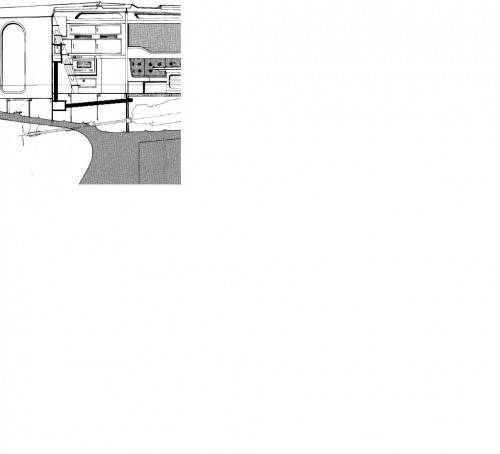
I attach a sketch showing the hoses, and ask you to measure if the heights given above can be achieved. If there is too little space behind the ladder, the separator could be moved to the aft side of the bulkhead, and the hose to the port side hull exit run through the head compartment
It appears that the Halyard web page is not working properly. If you can not find the measurements for the 3½" water lift and separator pls let me know.
Kind regards
Lars
 |
|
Join Date: 30 March 2019
Posts: 4 |
||
|---|---|---|
|
Dear Professor, actually on cassiopéia, bellow the lader are two diesel Tanks, so i would have to remove them to have the water lift here. aft the bulkhead are some shelves, i could remove the top one to run the hose thrue the head where i'll have to hide the hose. but i have no space above the aft cabin door to run the hose to the starboard exit.
not easy ....
Yann |
|
Join Date: 02 January 2008
Posts: 1547 |
||
|---|---|---|
|
Yann Thank you for the information. The 65's are very individual, and some of them do not have fuel tanks under the ladder.
How many fuel tanks are there totally, and where located?
How far out to SB the exhaust hose needs to move in reference to the engine exhaust bend for passing aft outside the tanks? Or could the hose be led port side of the tanks?
On some 65's there is about 30 cm height above the aft cabin door up to the deck on the forward side, but again there are differences.
Would you have suggestions for how to proceed?
Kind regards
Lars
|
- Threads : 1701
- Posts : 10215
- Members: 820
- Online Members: 0