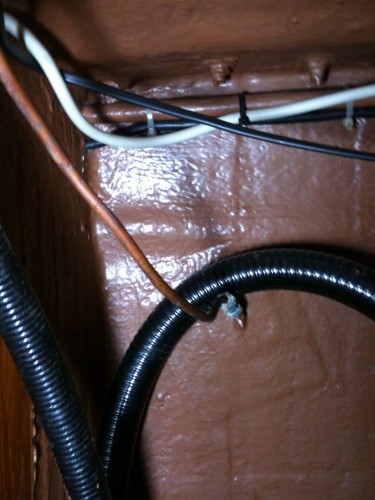
What is this pipe for? In the locker behind the chart table of our Swan 38 there is a small copper pipe ending in the hull, however there is no opening inthe hull on the outside?
I cannot see where it comes from or what it is used for.
That is the outboard discharge of the raw water coooling anti-siphon venting device. Behind the engine, where the exhaust manifold is, you should find an upward rubber gooseneck hose; the copper tubing you found starts from a tee at the highest point of the gooseneck. If the copper tubing is still attached to the anti-siphon tee I recommend to open again the outer aperture in correspondence to the copper tubing.
Yard people tend to consider that hole a blemish that needs to be closed with putty; on the contrary it is needed to avoid engine flooding.
Dear Paul and Daniel
It is likely that this is the mentioned vent line, but I would like to hear if Matteo and other Swan 38 owners have such a copper pipe, and whether it terminates in the recessed cove stripe? In that location it is less visible on the outside.
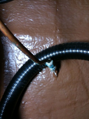
It is important to avoid water pockets in the vent line, and the bend visible near the hull needs to be straightened if the tube is in use. At higher engine rpms a little water can be expected to come out.
If the original engine has been replaced maybe the guys installing the new one did not use this vent line, and it has been left unconnected also at the other end. A siphon break of some sort is, however, necessary for wet exhaust engines installed below the waterline
Kind regards
Lars
It could be indeed a drain pipe for the spinnaker pole but then there should be another on the other side.
Regarding the cove stripe I think it runs a bit higher as a bulge in the vtr seems to confirm.
I would like to explain that I insist because in my 411 the anti-siphon vent tubing is exactly like the one showed in the pictures and its output is pretty visible on the outside. For the same reason, as I wrote, inexperienced yard workers tend to caulk the small hole and do quite a damage; this is what happened to Luna Menguante last spring when the antifouling was renewed.
As Lars suggests, the small tubing should not make kinks like in the pictures and there should not be wire conduits leaning on it.
Moreover as in my case it is a necessary and working vent, I periodically check its health. Being rather small it is easily plugged by salt or bugs (occasionally "two-legged Big Bugs").
Swanic, Paul's boat, is hull # 102, so she's one of the last 38's, and the pipe looks absolutely original. I think Daniel is right and it seems to me the vent pipe for the engine (it is lacking on my boat, hull 067). It would bve interesting to know which engine Swanic has installed, and if it is the original one.
Lars, the drain for the spinnaker poole recess, unless the Shipyard decided to get it higher than in older boats, like mine, is quite lower.
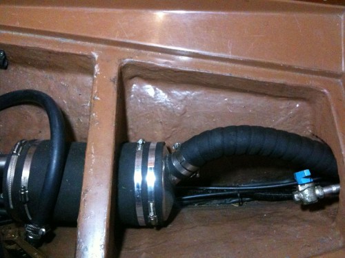
Is the connection on the right with the blue lever the connection where the copper pipe should connect to. There is indeed a new engine placed in 2006. I think the pipe is not in use any more but it might be good to reconnect it.
Is the connection on the right with the blue lever the connection where the copper pipe should connect to. There is indeed a new engine placed in 2006. I think the pipe is not in use any more but it might be good to reconnect it.
I cannot say for sure but I do not think so. In my boat a blue valve like that was used on the drain of the muffler and your picture suggests something like this.
The other side of the pipe we are talking about should be higher, namely above the water level of the boat (LWL).
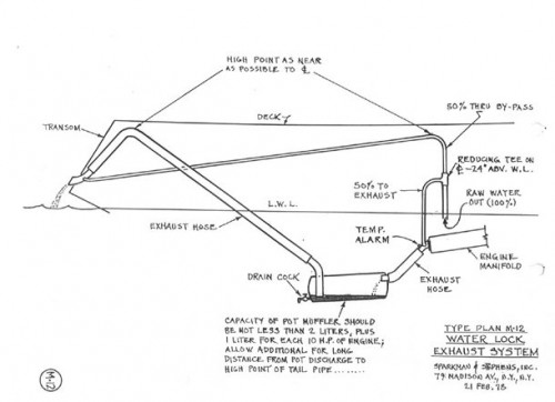
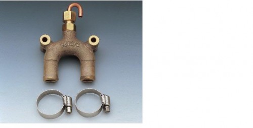
Just to stay on the subject I am enclosing an original S&S drawing showing how a good wet exhaust system should be designed. The anti-siphon function is performed by what is here called "50% THRU BYPASS".
Paul and Daniel
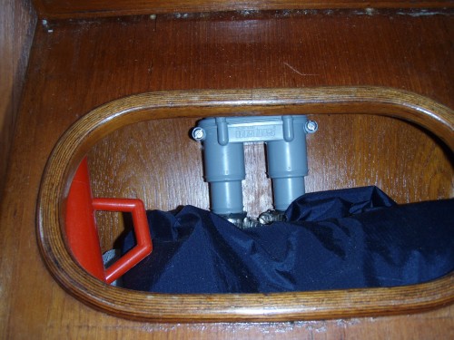
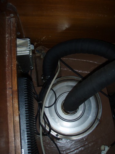
The waterlock looks like a Volvo, is the new engine of this brand? The siphon break sits on the bulkhead above the engine, and if it also comes from Volvo it may look as shown below. There are two hoses up to the siphon break connections, inside there is a valve, and probably no copper pipe led to the outside. The siphon break valve requires maintenance while a copper pipe does not.
Referring to the valve with the blue handle aft of the waterlock this may be the drain cock for a second waterlock further aft?
Kind regards
Lars
This is why I like this forum. So much knowledge available.
The pipe in the locker behind the chart table is definitely not the drain of the spinaker pole. There are in the same locker two blake seacock's, one for the spinaker pole and one for the electric bilge pump. (I have recently serviced all the twelf seacock's of which only four were working). There is one on the opposite side also(only reachable by taking out almost the entire cupboard which is why it had not been serviced for 30 years I think!!)
So the copper pipe must be the pipe of the anti siphon venting device.
The engine is replaced I think in 2006 by a Sole mini 33 ( Mitsubishi). This was after the volvo penta installed in 2001 whas damaged by water in the exhaust system probably because the anti siphon was not correctly installed. By the way the yard attached the cooling water inlet too two seacock's because of the small diameter of each seacock. So there is no salt water inlet for my kitchen.
In the attached picture you can see the siphon currently installed under the entrance. It is a vetus system with a valve mechanism.
The blue valve is i think indeed for draining the muffler which is very near to it. A picture is enclosed.
I still do not know where to find the other end of the copper pipe? i think it is a better system than the current system so I would like to re install it. Can anyone post a picture of the original system?
a very strong and seawater stabile bronce vent ( quality is like the Blake valves) is available from Groco Marine Products (see www.groco.net chapter SANITATION / TOILET)
They have a large diameter for easy cleaning and you need no drainage pipe trough the hull. Additionally the have a beautiful classic look.
Paulus,
my guess is that you should be able to find the other end of the copper tubing in the neighborhood of the present anti-siphon loop and the Vetus vent.
If you plan to restore the copper tubing be sure that it is free of impediments and as straight as possible (no kinks).
I think that when I will have to substitute mine I will use a slightly larger hose and, maybe, not copper.
1. Toilet outlet
2. Toilet inlet
3. Discharge electric Blige pomp (cabin behind chart table)
4. Drainage of spinnaker pole port (cabin behind chart table)
5. Drainage of spinnaker pole starboard (under cupboard)
6. Drainage of sink in kitchen
7. Inlet salt water tap ( now engine cooling)
8. Inlet engine cooling
9. Drainage Of cockpit port
10. Drainage of cockpit starboard
11. Drainage of gasbun and i think two hoses from the battery box
12. Aft of the cockpit drainage seacock port ( Will Find out what it is used for)
13. Aft of the cockpit drainage seacock starboard ( Will Find out what it is used for)
Paul
It appears the Volvo waterlock has been left in place when installing the waterlock for the present engine, so now you have two.
You mention a sea cock for the electrical bilge pump.
I would like to ask about the arrangement - is the sea cock below or above the water surface, and is there a siphon break on the hose?
Referring to the inlet for the salt water tap now used for engine cooling - suggest you could branch off a hose to the salt water tap.
Gas and battery boxes drained to a sea cock sounds strange. Both need to be drained to the outside air, gas both downwards (above static water surface) and upwards, battery boxes upwards.
Kind regards
Lars
There are 5 seacock's below the waterline. Engine x2, toilet x2, sink in kitchen.
All the other seacock's All original Blake's are above the waterline. I don't know why they are there, but they are definitely original installed by nautor.
For example, who woud want to close the seacock of THE cockpit drainage unless you want to use it as � bathtub?
Paul
Thank you for the information.
The electric bilge pump system works fine as long as the sea cock is above the water surface, but pls note that if the yacht heels so the sea cock goes under, a siphon is created when the pump is working. When the pump stops water may then siphon back. Check valves are seldom fully tight because of debris in the bilge - reason to keep it clean.
Referring to the cockpit drains there were strong opinions at the time of build that even if they are above water sea cocks are needed if the drain hose fails. Now it is not a requirement, but without sea cocks it can be recommended that suitable wooden plugs are kept ready.
Kind regards
Lars
Lars and Paul,
you are rising an interesting issue I often thought about. All my boats (including the present) have had seacocks in the cockpit drains and I always wondered how would I operate them in an emergency: they are never used so they are probably frozen, moreover they are so recessed that reaching them before it is too late may be impossible.
My deliberately polemical conclusion was that they are required by some very general rule of register certification which, applied to this particular case, does not make sense; is it so?
It would be sensible to think about possible failures happening there and find a different solution than those useless recessed seacoks. Maybe a way of remotely operate them.
...notwithstanding I am ready to reconsider if, as Paul says, one likes to have a jacuzzi in the boat!